Memory Game
Made by Aritro S, Byron Z, Haris K
Made for Arduino Project assignment (TEJ3M0)
Project Description
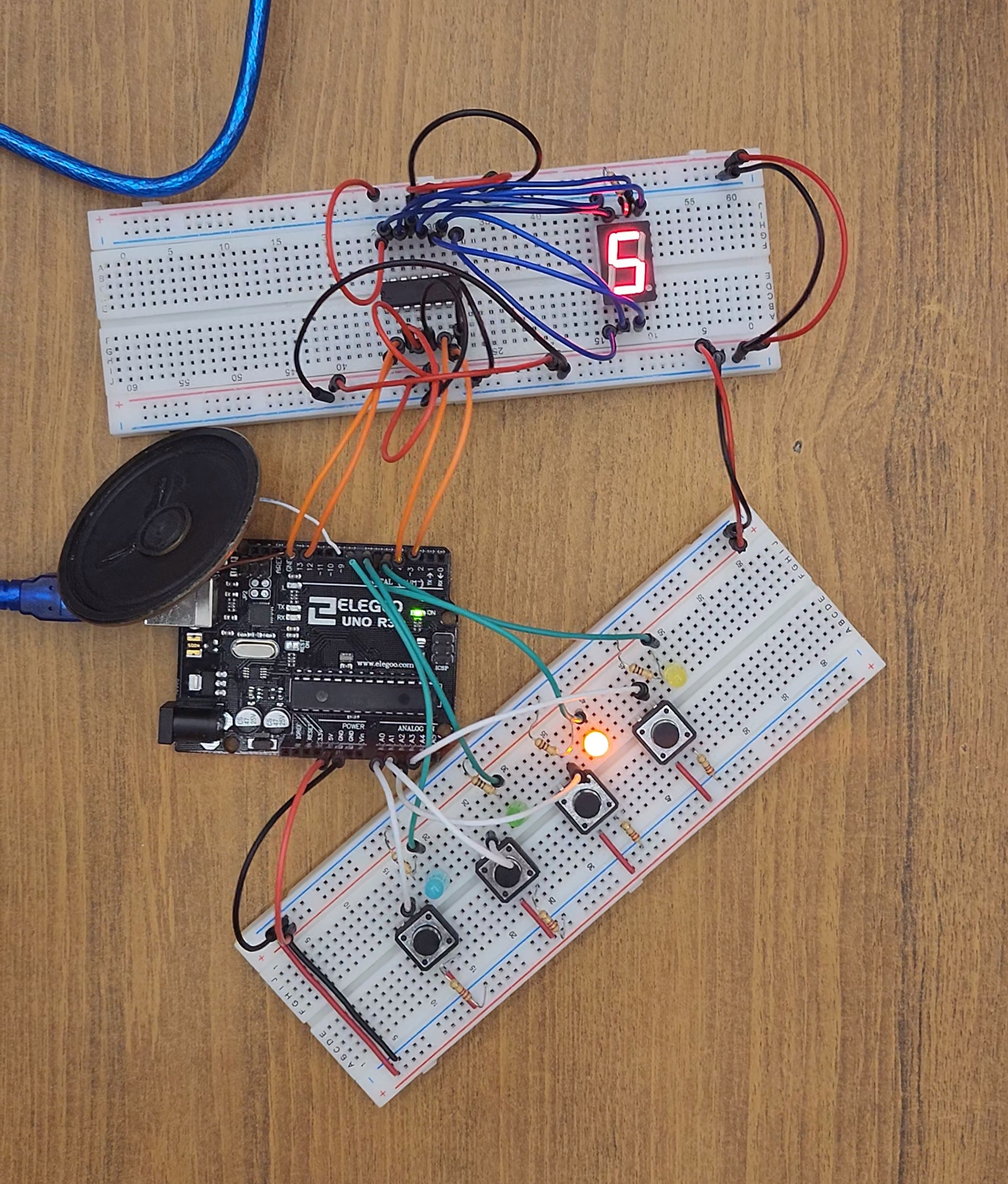
The project that we chose for our Arduino project was a memory game. The single player game involves the circuit turning on and playing sounds in a specific sequence, requiring the player to replay that sequence in the correct order to proceed to the next level. It uses four buttons to input the sequence, four differently colored LEDs to indicate which button to press, a buzzer to play sounds, and a 7 segment display to show the user's current score. The game has 10 levels, and the player wins if they can complete them all. These levels are also randomly generated each time to provide a unique experience to the player. This project is completely original, and we didn't follow any online walkthroughs or guides in order to make either the circuit or the code.
TinkerCAD Simulation
Pictures and Videos of Circuit
Parts List
| Name | Quantity | Picture |
|---|---|---|
| Arduino Uno | 1 | 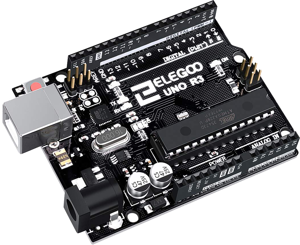 |
| 7 Segment Display (Cathode) | 1 | 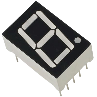 |
| 7 Segment Decoder (CD4511) | 1 | 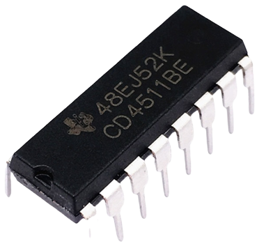 |
| LED (Blue) | 1 |  |
| LED (Orange) | 1 | 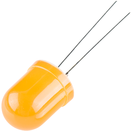 |
| LED (Red) | 1 | 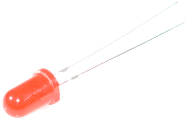 |
| LED (Yellow) | 1 | 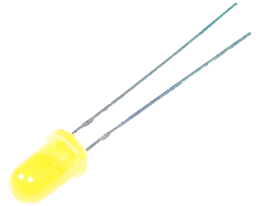 |
| Pushbutton | 4 | 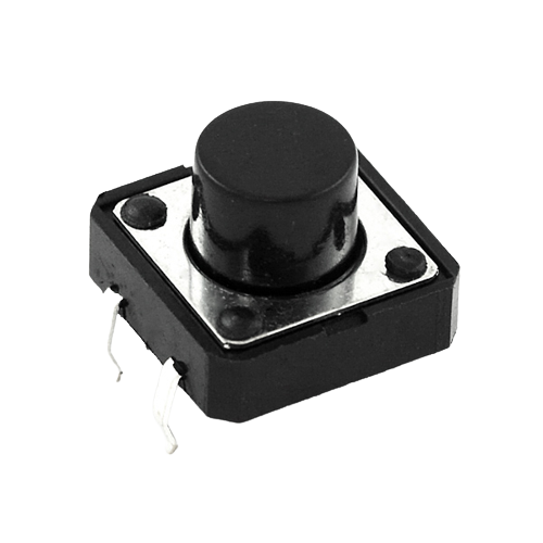 |
| Resistor (200Ω) | 1 | 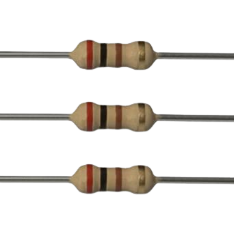 |
| Resistor (220Ω) | 4 | 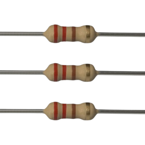 |
| Resistor (330Ω) | 4 | 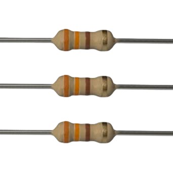 |
| Speaker | 1 | 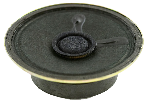 |
Daily Log
Reflection
What we did well
After researching unique key components for the project, developing a solid plan, and solving problems along the way,
we were able to successfully complete the Memory Game. Throughout this project, we achieved many of our goals as well as refined our knowledge in computer engineering and technology.
Following reflection of this circuit project, we identified many successes. These include our excellent organizational skills, innovation and risk-taking mindsets, conflict resolution abilities,
and finally our collaborative capabilities - how we worked efficiently as a team.
With this project, we surmounted organization by having highly neat and tidy circuitry. For one, we stripped fresh voltage and ground wires to reduce the number of protruding jumper wires covering the main circuit components.
In addition, we also stripped the resistors and LEDs to make them appear more integrated into the breadboard. In terms of hardware, we had also colour-coded our jumper wires in our TinkerCAD sketch for easy identification; for example, we used white
wires for the buttons, green wires for the LEDs, orange wires for CD4511 inputs, and finally blue wires for the remaining connections. However, hardware was not the only aspect that revealed our profound organizational skills.
Our code was highly organized with relevant comments to describe each section of the program. We also appropriately used variables and conditional statements when needed. For these reasons, we strongly displayed organizational skills
in this project.
Furthermore, we displayed astute qualitites of innovation and risk-taking as we selected a project without prior knowledge of the main components. Especially with the usage of the integrated circuits,
like the 75HC595 and the CD4511, we researched about how they worked and how they could contribute to our project. Paired with each of these IC components, we had to learn more about binary functions within the programming aspect to properly
control the circuit as well as debug errors. We evidently displayed huge success with the circuitry and clearly showed progress in our learning.
Moreover, during this project, we also faced many tribulations that incurred as a result of the high complexity of the memory game. For instance, one main issue we faced with during the project was the inconsistency of the 75HC595. This integrated circuit is known
for its powerful ability to shift bits by one binary value; however, it appeared to not always function as it oftentimes failed to even power the 7 segment display. On the first occasion, this was actually as a result of the IC being fried. Thus, we replaced the circuit
with a working one to resolve this problem. Despite debugging by utilizing bit functions to output relevant data to the serial monitor, we still noticed rare success with this chip. Hence, we decided as a team to transition to the implementation of the CD4511
since it was more reliable and more appropriate for the 7 segment display. As a result, not only were we able to resolve the main issue using various strategies and methods, but we were actually able to improve the design for greater precision.
Finally, our ability to collaborate was outshown in this project. We displayed excellent cooperative skills by effectively brainstorming and contributing ideas together as a team. In regards to communication, we were able to surmount communication barriers by using
social platforms like Discord to continue to share ideas even outside of class. We were also able to apply such ideas together using tools like GitHub and Visual Studio Code. To elaborate, we were able to store each of our contributions in a repository on GitHub, while
also being able to build our website, logs, and code using Visual Studio Code's collaborative tool - Live Share. With our collaborational skills, we evidently produced a powerful final product in this project.
What we can improve on
To begin, what we could've improved on is doing prior research on the Shift Register (75HC595).
Since the example circuit for our Memory Game used a Shift Register, we decided to just go along with that.
However, we didn't realize how much trouble it would be to use the Shift Register,
in fact, the first one we used was dead and were not able to figure that out for an entire day.
After we got another Shift Register to work, it didn't power the 7 Segment Display properly and we had to find an alternative.
Thus, we searched online and found that a 7 Segment Latch Decoder (CD4511) would work much better with the 7 Segment Display.
Had we just done a bit of research before trying to build the circuit, we would've had a lot less trouble finishing the project.
Additionally, we could've added more complexity to the circuit. Although our circuit is decent in terms of complexity,
it would've been better if we added more components and made the code more advanced as well.
After trimming the wires, there was quite a lot of space that could've been used for more components such as another 7 segment display, more LEDs, and more buttons.
Adding these components would've made the game more complicated and perhaps more fun because we could've added more levels (displayed on the 7 segment displays)
and made the amount of memorization longer and more difficult (more LEDs and buttons).
However, we didn't have enough time to do so. Additionally, if some components ended up not working or the code ended up causing issues,
it would've made troubleshooting a longer process. Thus, we had reason to not add more complexity.
Moreover, better wire management could've made the circuit look nicer.
Although we cut wires for both 5V and Ground wires, there was still a lot of jumper wires for each individual component connected to the Arduino.
A reason we didn't cut wires for each component was because, like adding more complexity, we didn't have enough time.
Cutting wires is a long and arduous process and the amount of wires needed to be cut can be seen from the images of the circuit.
If we ended up cutting a wire too short or too long, we would've wasted wires which could've been better used elsewhere.
Thus, we also had reason to not do more wire management.
Finally, instead of using functions from the Arduino library such as pinMode and digitalWrite, we could've directly interfaced with the Arduino's internal registers. While the Arduino IDE provides high level functions that are simple to use, they can end up requiring both more memory and more clock cycles. While this isn't too important in most applications, if we were to further expand our project, we might run into a situation where the effects of such optimization are tangible. To do this, we could shift specific bits at certain memory addresses, defined by the ATMega328p's datasheet (the microcontroller that powers the Arduino Uno R3).
For example, instead of running digitalWrite(13, HIGH), we could do PORTB |= (1 << PORTB5). This sets the bit in the register that controls pin 13 (otherwise known as PORTB5 for the ATMega328P) to 1, sending 5V to anything connected to that pin.
While they do the same thing, there is a major performance difference, the latter running 40x faster than the former (source). By directly manipulating the registers that control the pins, we could vastly improve the performance of our code. However, we also had reason to not do this. Since our code wasn't too heavy, it wouldn't have a significant difference in the player's experience. In addition, it would make our code more difficult to debug,
which wouldn't be a good idea considering our limited time frame.
More Info
You can view more info about this project on our GitHub repository.